On this page
Overview
- Data-centre MEP uses N, N+1, 2N, and other project-defined topologies to balance availability objectives, maintainability, space, energy, and capital cost.
- Electrical supply, distribution, cooling and controls must be reviewed together under the defined operating and failure scenarios.
- Uptime Institute Tiers describe infrastructure outcomes. Redundancy labels alone do not establish a Tier.
- MEP density and redundant paths make disciplined BIM coordination and issue closure important for reducing field-change risk.
Data center MEP design brings together the power, cooling and building systems that support the IT equipment. The starting point is the load and the required availability, including maintenance and failure conditions. Climate, utilities, space and future growth also shape the design.
Start with the MEP design basis
A credible data center or data centre MEP design starts with the IT load profile, rack densities, growth stages, availability objective, climate, utility constraints, water strategy, maintainability plan, and commissioning criteria. These inputs become the design basis that controls electrical topology, cooling architecture, plant space, distribution paths, controls, and the BIM coordination model.
Scroll sideways to compare
| Design input | MEP decision |
|---|---|
| IT load and rack-density schedule | Electrical capacity, cooling method, distribution and phasing |
| Availability and maintenance objective | Resilience topology, isolation, bypasses and concurrent-maintenance strategy |
| Climate, water and energy constraints | Heat-rejection system, economisation and operating setpoints |
| Commissioning and failure scenarios | Controls sequence, sensors, test points and acceptance evidence |
Regional project context belongs in the design basis
A market name is not a design standard. The project team must record the governing jurisdiction, authority having jurisdiction, owner criteria, adopted codes, units, climate data, utility conditions, professional responsibilities, and acceptance route for the specific site.
Scroll sideways to compare
| Project context | Inputs to record | Authority that remains project-specific |
|---|---|---|
| United States and the Americas | State, province or national jurisdiction; AHJ and utility requirements; owner standards; I-P or SI units; climate and site hazards | Locally appointed professionals, the owner, utility, commissioning authority, assessor and AHJ retain their contracted review and approval roles |
| Middle East | Country, emirate or municipality; employer and consultant requirements; utility and fire-authority criteria; ambient heat, dust, water and heat-rejection assumptions | The appointed local consultants, authorities, utilities, assessors and contractors retain statutory, certification and installation responsibilities |
| Europe | Country-specific rules; owner information requirements; SI units; climate, energy, water and heat-reuse objectives; national reporting context | The locally appointed designers, reviewers, assessors and authorities retain professional, regulatory and certification responsibilities |
Redundancy: N, N+1, 2N
- N: the capacity needed to serve the defined load, without spare capacity in that arrangement.
- N+1: one additional capacity unit. The design still needs checks of distribution paths, controls and shared dependencies.
- 2N: two systems, each sized for the full defined load. Assess their independence and the response to maintenance and failure.
- Other arrangements need the same review of operating scenarios. A redundancy label alone does not establish uptime or a Tier classification.
Power and cooling systems
A data center power design can include utility and standby supplies, transfer equipment, UPS systems and distribution to the racks. Their arrangement depends on the required operating and failure scenarios; they are not simply one series chain. Review electrical and cooling dependencies together. Redundant equipment does not, by itself, guarantee uninterrupted operation.
MEP coordination and commissioning deliverables
- Design-basis report, load schedules, system narratives and single-line diagrams tied to the agreed resilience objective.
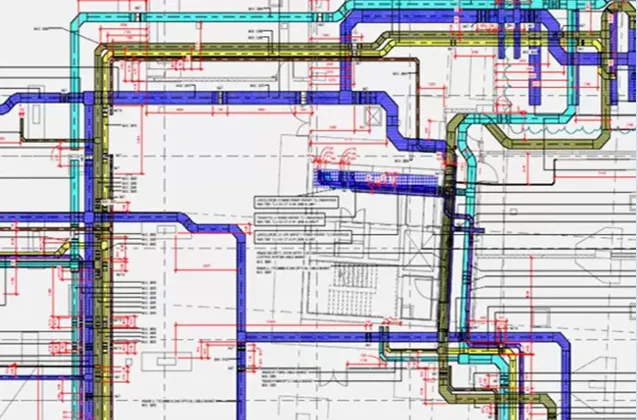
- Coordinated power, cooling, controls, containment and cable-routing models with maintainability and replacement clearances.
- Failure-mode and sequence-of-operations reviews covering utility loss, equipment outage, maintenance isolation and restart.
- Commissioning-ready points lists, sensor locations, test scripts, setpoints and acceptance criteria.
- Energy and water performance inputs suitable for the applicable national, authority, owner or client reporting requirements.
Scroll sideways to compare
| Tier | Outcome | Design implication |
|---|---|---|
| Tier I | Basic Capacity | Dedicated site infrastructure supports the IT environment |
| Tier II | Redundant Capacity Components | Redundant critical components reduce disruption from equipment failure |
| Tier III | Concurrently Maintainable | Planned maintenance can occur without shutting down the critical environment |
| Tier IV | Fault Tolerant | A single failure does not interrupt the critical environment |
Mission-critical, coordinated
Our data center engineering service covers MEP design, coordination and agreed analysis work. For an airflow study, start with the CFD inputs and review checks. We agree the scope and approval responsibilities with your team before work begins.
Technical references
Sources for the definitions and design context discussed here. Check the applicable edition and project requirements before using them in design.
- 01Tier Classification SystemUptime Institute
- 02
- 03AI Data Center Energy Performance FrameworkPNNL, ASHRAE and NEMA
- 04Dubai Building CodeDubai Municipality
- 05Saudi Building CodeSaudi Building Code Center
- 06EU Code of Conduct for Data CentresEuropean Commission Joint Research Centre