On this page
Overview
- CFD helps identify possible hot spots and airflow problems under the operating conditions included in the model.
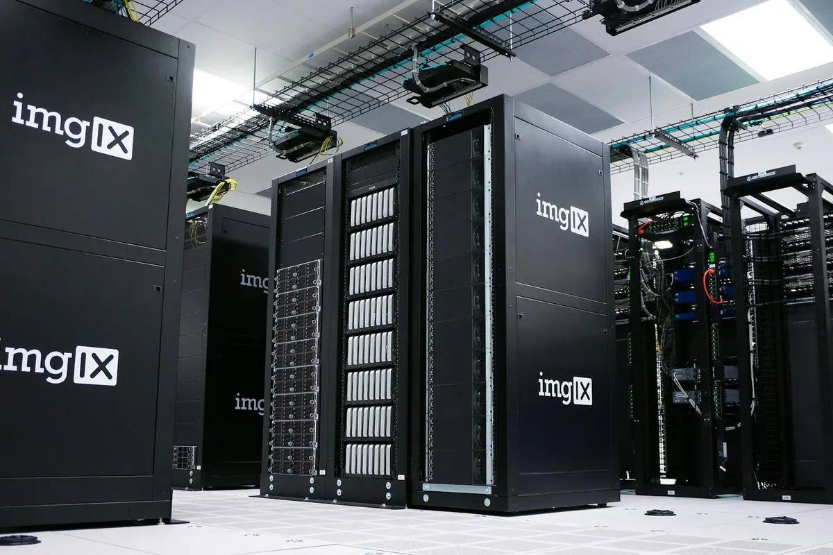
- Hot-aisle or cold-aisle containment limits mixing between supply air and rack exhaust. Leakage and airflow balance still need to be checked.
- PUE measures whole-facility overhead; CFD supports cooling efficiency, but the project target must reflect climate, load profile, resilience, and measurement boundary.
- High-density racks may require liquid cooling. Select the approach against the IT equipment requirements and site design basis.
Data center CFD simulates airflow, pressure and temperature under selected operating conditions. It helps the team investigate hot spots, recirculation and equipment outages before construction. Results depend on the input data, modeling assumptions and checks used in the study.
CFD inputs and boundary conditions
A data center CFD model is only as reliable as its inputs. The design team should record room geometry and leakage assumptions, rack-by-rack heat release and airflow, fan curves, supply-air conditions, pressure boundaries, containment details, floor or ceiling distribution, controls logic, and the operating or failure scenarios to be tested. Every result should be traceable to this basis.
Scroll sideways to compare
| Input | What it controls |
|---|---|
| Rack load, airflow and inlet envelope | Heat source strength and the acceptance limit at IT intakes |
| Cooling-unit duty, fan curve and setpoint | Available cooling and air-delivery behaviour |
| Containment, leakage and openings | Bypass, recirculation and pressure balance |
| Normal, growth and equipment-outage cases | Performance across design life and resilience scenarios |
| Mesh strategy and solver controls | Numerical resolution, convergence and repeatability |
Containment: limit air mixing
Containment separates the cold supply path from the hot exhaust path. Gaps, unused rack spaces and unbalanced air supply can still allow mixing or bypass. Model those details and check them during commissioning rather than assuming containment seals the room perfectly.
What CFD reveals
- Hot spots: racks or zones with high predicted inlet temperatures in a modeled scenario.
- Bypass and recirculation: cold air short-circuiting back to the units, or hot air recirculating into intakes.
- Effect of failures: what happens to temperatures when a CRAC unit drops (the redundancy scenario).
- Optimisation: floor-tile placement, containment, and setpoints tuned for efficiency before commissioning.
How CFD results are verified
- Check mass and energy balance so the model accounts for supplied air, return air, IT heat and cooling duty.
- Demonstrate stable convergence and repeat key results with a refined mesh where gradients are high.
- Review rack-inlet temperatures, airflow distribution, bypass and recirculation against project-defined acceptance criteria.
- Test credible failure and growth scenarios, not only the ideal full-capacity operating case.
- Compare the commissioned facility with the model using calibrated sensor locations and document any model updates.
CFD study workflow and reviewable deliverables
Scroll sideways to compare
| Stage | Reviewable evidence |
|---|---|
| Study basis | Input register, source files, assumptions, exclusions, acceptance criteria and named normal, growth and failure scenarios |
| Model preparation | Geometry simplifications, rack heat and airflow schedule, cooling-unit data, leakage, openings, containment and pressure boundaries |
| Numerical quality | Mesh strategy, local refinement, solver settings, convergence history, residuals and mass-and-energy balance |
| Results | Rack-inlet temperature maps, airflow and pressure distribution, bypass and recirculation findings, hotspot list and scenario comparison |
| Design response | Recommended changes linked to the affected scenario, model revision and responsible design discipline |
| Commissioning correlation | Sensor locations, test conditions, measured-versus-model comparison method, tolerances and model-update rules |
The shift to liquid cooling
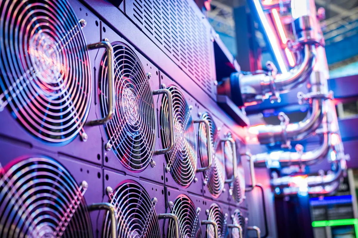
Some AI and high-performance computing equipment needs liquid-based cooling. Rear-door heat exchangers, direct-to-chip and immersion systems have different interfaces and operating requirements. Choose the method with the IT and cooling suppliers, then coordinate coolant distribution, heat rejection, leak management and maintenance.
Regional project and climate context
The physics does not change by market, but the design weather, utility and water constraints, owner criteria, adopted codes, reporting context, and review authority do. The study basis should identify the exact project location and controlling requirements instead of relying on a regional label.
Scroll sideways to compare
| Project context | Inputs to confirm | Boundary of the CFD work |
|---|---|---|
| United States and the Americas | Project climate data, owner thermal envelope, AHJ and utility requirements, rack roadmap, resilience objective and I-P or SI units | ASHRAE resources can inform the study basis where adopted; the owner, appointed designers, commissioning authority and AHJ retain their defined roles |
| Middle East | Peak and coincident ambient conditions, dust and filtration, water availability, heat-rejection performance, utility constraints and country or municipal requirements | Dubai, Saudi and other jurisdictions have distinct requirements; no single “Middle East standard” or CFD result substitutes for local review and approval |
| Europe | National requirements, SI units, climate, energy and water objectives, heat-reuse opportunities, reporting boundary and owner information requirements | The European Commission JRC Code of Conduct is voluntary guidance; national rules, the project brief and appointed reviewers remain controlling |
Cooling scenarios evaluated before construction
Spetia can coordinate cooling in BIM and use CFD to evaluate documented airflow, temperature, containment, and failure scenarios before construction, with assumptions and acceptance criteria visible to the project reviewers.
Technical references
Sources for the definitions and design context discussed here. Check the applicable edition and project requirements before using them in design.
- 01Power Usage Effectiveness (PUE)The Green Grid
- 02
- 03
- 04AI Data Center Energy Performance FrameworkPNNL, ASHRAE and NEMA
- 05Dubai Building CodeDubai Municipality
- 06Saudi Building CodeSaudi Building Code Center
- 07EU Code of Conduct for Data CentresEuropean Commission Joint Research Centre